
Abstract
Si has been considered as one of the most attractive anode materials for Li-ion batteries (LIBs) because of its high gravimetric and volumetric capacity. Importantly, it is also abundant, cheap, and environmentally benign. In this review, we summarized the recent progress in developments of Si anode materials. First, the electrochemical reaction and failure are outlined, and then, we summarized various methods for improving the battery performance, including those of nanostructuring, alloying, forming hierarchic structures, and using suitable binders. We hope that this review can be of benefit to more intensive investigation of Si-based anode materials.
1 Introduction
In the last two decades, the Li-ion batteries (LIBs) have successfully captured the portable electronic market. However, when it is proposed to conquer the upcoming markets of electric vehicles, storage of energy from renewable energy sources, such as photovoltaic plants and/or wind turbines and other KWh levels load, great improvements in storage capacity, which is currently mainly limited by their electrode materials, are urgently needed [1–5]. It is well known that the commercial graphite anode cannot meet these challenges due to its low theoretical capacity (372 mAh g−1). There is a consensus that the breakthrough in capacity can be achieved by moving from classical intercalation reaction to alloying reaction because the alloying reaction can store more Li compared with intercalation reaction. For example, Li can react with Si to form Li22Si5 alloy, but with graphite only, to form LiC6 alloy. Since Dey demonstrated that Li metal can electrochemically alloy with other metals (Sn, Pb, Al, Au, Pt, Zn, Ag, Mg, and Cd) at room temperature [6], Li-alloying reactions with metallic or semi-metallic elements and various compounds have been investigated during the past few decades, such as Sn, P, Ge, Pb, and Sb. Wen et al. showed that Sn reacted with lithium to yield different Li–Sn phases: Li2Sn5, LiSn, Li7Sn3, Li5Sn2, Li13Sn5, Li7Sn2, and Li22Sn5. A black P/C nanocomposite also showed high capacity (about 2,000 mAh g−1) [3]. Among the various Li alloy elements, Si has been considered as one of the most attractive anode materials for LIBs, not only because of its high gravimetric (4,200 mAh g−1) and volumetric capacity (2,400 mAh cm−3), but also due to its abundance, cheapness, and environmentally benign property, as shown in Table 1. However, it suffers from fast capacity fading, which greatly hampers the application of Si anode materials.
1.1 The Mechanism of Electrochemical Lithiation
LIBs are mainly composed of anode (generally graphite), a carbonate-based organic electrolyte, and a cathode (generally LiCoO2). Li ions are intercalated and deintercalated between graphite and LiCoO2 through the electrolyte during discharge and charge. The theoretical capacities of anode and cathode are 372 mAh g−1 (graphite) and less than 160 mAh g−1 (LiCoO2), respectively, which are too low, especially for anode material. Si anode is very attractive because of its high theoretical capacity of 4,200 mAh g−1 which is 10 times more than that of commercial graphite [3]. Moreover, the discharging potential is about 0.2 V with respect to Li/Li+, which is lower than most of other alloy-type and metal oxide anodes [7]. Furthermore, it is safer and stabler than graphite (lithiated silicon is more stable in typical electrolytes than lithiated graphite) [8].
The mechanism of electrochemical lithiation of Si is critical to improve the performance of Si anode, which has been investigated by several groups [9–16]. It is found that the reactions follow the equilibrium Li–Si binary phase diagram at high temperature, forming different intermetallic compounds and showing distinct voltage plateaus for each two-phase region [17]. However, there is only a two-phase region at about 0.1 V at room temperature during first discharge process [18], as shown in Fig. 1. It should be noted that the two-phase region disappears after first cycle. In order to find out the lithiation mechanism, X-ray diffraction (XRD) analysis was performed to investigate the phase transition [13–15], and the reaction mechanism is explained as follows:

Voltage profiles of Si powder electrode for the first and second discharge/charge cycles [18]
During discharge
During charge
In the two-phase region, crystalline Si becomes amorphous Li–Si alloy during the first lithiation (1), and the highly lithiated amorphous LixSi phase is suddenly found to crystallize into Li15Si4 phase around 60 mV (vs. Li/Li+) (2). Another two-phase region appears during the first delithiation process, and the final product is amorphous Si (3). There are also amounts of residual Li15Si4 phase after the first delithiation, which can be avoided if the potential of the Si electrode is controlled above 70 mV during cycling. When Li ions react with the amorphous Si during the second cycle, the two-phase region disappears, and slo** voltage plateaus are observed, which indicates single-phase region. After the second cycle, reactions (2) and (3) were repeated, show the above features repeatedly, and reversible capacity faded quickly.
1.2 The Failure Mechanism
Although Si has the highest theoretical capacity, its cycling performance is very poor. Figure 2 shows the charge–discharge profiles of Si powder anode at a current density of 100 mA g−1. It could be found that a large amount of irreversible capacity appears in the first cycle. The first discharging capacity is about 3,260 mAh g−1 but that of the charging is only 1,170 mAh g−1. After 10 cycles, only very low capacity (about 200 mAh g−1) can be retained. To understand the reasons for the poor cycling stability of Si anode, the failure mechanism has been investigated by several groups [16, 19]. The conclusions can be drawn as follows:

Charge–discharge voltage profiles of Si powder anode [16]
-
a.
The large change in the volume of Si anodes, which increases internal resistance and loss of contact area between Si and conductive materials, is considered to be the main reason for their rapid capacity loss. Figure 3 shows the schematic of morphologic changes that occur in Si during electrochemical cycling [20]. The volume of Si anodes changes by about 400 % during cycling. As a result, Si films and particles tend to undergo pulverization during cycling. Most of the material loses contact with the current collector, resulting in poor transport of electrons.
Fig. 3 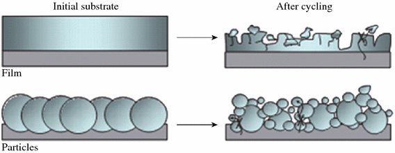
Schematic of morphologic changes that occur in Si during electrochemical cycling [20]
-
b.
Solid electrolyte interphase (SEI) stability at the interface between the silicon and the liquid electrolyte is also responsible for the failure of the Si anode. The SEI layer is formed during battery discharging, due to electrolyte decomposition on the surface of anode at the low potential. As shown in Fig. 4, a thin layer of SEI is formed in the lithiated and expanded state [21]. During delithiation, the Si particle shrinks, and the SEI layer breaks down into separate pieces, and fresh Si surface is exposed to the electrolyte. In later cycles, new SEI layer continues to be formed on the newly exposed silicon surfaces. The SEI is an electronic insulator but a Li–ion conductor, and so the growth of the SEI layer is eventually terminated at a certain thickness. The thick SEI layer is harmful for the cycle life, because it can cause a rise of the electrode impedance/polarization and decrease of the electrode’s electrochemical reactivity. As discussed above, a large volume change and unstable formation of SEI film are the main issues for the failure of Si anode.
Fig. 4 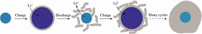
Schematic of SEI formation on silicon surfaces [21]


2 The Methods to Improve the Battery Performance
2.1 Si Nanostructures
Tremendous efforts have been made to improve the batteries performance of Si anode. In order to overcome the volume change during electrochemical reaction, many researches are focused on accommodating the volume changes in the earlier studies. Nanomaterials have the genuine potential to make a significant impact on the electrochemical performance of Si anode [22], as their reduced dimensions enable far higher intercalation/deintercalation rates. In addition, the volume change can be also buffered after downsizing the Si particle to nano-size. The significance of nano-sized Si on battery performance was demonstrated by several groups. Li et al. reported that a nano-Si (78 nm) powder anode showed better capacity retention than bulk Si powder [23]. Kim et al. also synthesized Si nanoparticles with various sizes (5, 10, and 20 nm) and studied their battery performance [24]. The results indicated that 10-nm-sized Si showed the highest capacity retention among the samples, as shown in Fig. 5.

a Voltage profiles of 5, 10, and 20-nm-sized Si and 10-nm-sized Si after carbon coating during the first cycle in coin-type half-cells at a rate of 0.2 C between 0 and 1.5 V. b Plot of charge capacity versus cycle number (red: 5 nm, blue: 10 nm, orange: 10 nm after carbon coating, black circles: 20 nm) [24]. (Color figure online)
One-dimensional (1D) nanowires and nanotubes are also intriguing structures with good cycle stability. Cui et al. synthesized Si nanowires which were grown directly on the metallic current collector substrate [20]. The limited nanowire diameter allows for better accommodation of the large volume change and provides 1D electronic pathways allowing for efficient charge transport. The Si nanowires display high capacities at higher current density. Even at the 1 C rate, the capacities remain 2,100 mAh g−1, and a reversible capacity of over 3,000 mAh g−1 is maintained after 10 cycles. An array of sealed Si nanotubes is also prepared by CVD of Si on to ZnO nanorods and selective removal of ZnO (see Fig. 6) [73, 74].
In addition, the electrolyte offers a promising field for more extensive research efforts. It is found that the electrolyte containing VC or FEC has been recognized to favor the formation of more stable SEI film. Furthermore, the fabrication cost of nano-structured Si remains high and needs to be reduced for its practical applications.
References
B. Dunn, H. Kamath, J.M. Tarascon, Electrical energy storage for the grid: a battery of choices. Science 334(6058), 928–935 (2011). doi:10.1126/science.1212741
K. Kang, Y.S. Meng, J. Bréger, C.P. Grey, G. Ceder, Electrodes with high power and high capacity for rechargeable lithium batteries. Science 311(5763), 977–980 (2006). doi:10.1126/science.1122152
C.M. Park, J.H. Kim, H. Kim, H.J. Sohn, Li-alloy based anode materials for Li secondary batteries. Chem. Soc. Rev. 39(8), 3115–3141 (2010). doi:10.1039/b919877f
N.S. Choi, Z. Chen, S.A. Freunberger, X. Ji, Y.K. Sun, K. Amine, G. Yushin, L.F. Nazar, J. Cho, P.G. Bruce, Challenges facing lithium batteries and electrical double-layer capacitors. Angew. Chem. Int. Ed. 51(40), 9994–10024 (2012). doi:10.1002/anie.201201429
L. Wang, X. He, J. Li, W. Sun, J. Gao, J. Guo, C. Jiang, Nano-structured phosphorus composite as high-capacity anode materials for lithium batteries. Angew. Chem. Int. Ed. 51(36), 9034–9037 (2012). doi:10.1002/anie.201204591
A.N. Dey, Electrochemical alloying of lithium in organic electrolytes. J. Electrochem. Soc. 118(10), 1547–1549 (1971). doi:10.1149/1.2407783
X. Su, Q. Wu, J. Li, X. **ao, A. Lott, W. Lu, B.W. Sheldon, J. Wu, Silicon-based nanomaterials for lithium-ion batteries: A review. Adv. Energy Mater. 4(1), 1–23 (2014). doi:10.1002/aenm.201300882
Y.X. Yin, L.J. Wan, Y.G. Guo, Silicon-based nanomaterials for lithium-ion batteries. Chin. Sci. Bull. 57(32), 4104–4110 (2012). doi:10.1007/s11434-012-5017-2
B. Gao, S. Sinha, L. Fleming, O. Zhou, Alloy formation in nanostructured silicon. Adv. Mater. 13(11), 816–819 (2001). doi:10.1002/1521-4095(200106)13:11<816:AID-ADMA816>3.0.CO;2-P
H. Li, X. Huang, L. Chen, G. Zhou, Z. Zhang, D. Yu, Y.J. Mo, N. Pei, The crystal structural evolution of nano-Si anode caused by lithium insertion and extraction at room temperature. Solid State Ionics 135(1–4), 181–191 (2000). doi:10.1016/S0167-2738(00)00362-3
P. Limthongkul, Y.I. Jang, N.J. Dudney, Y.M. Chiang, Electrochemically-driven solid-state amorphization in lithium-silicon alloys and implications for lithium storage. Acta Mater. 51(4), 1103–1113 (2003). doi:10.1016/S1359-6454(02)00514-1
A. Netz, R.A. Huggins, W. Weppner, The formation and properties of amorphous silicon as negative electrode reactant in lithium systems. J. Power Sources 119–121, 95–100 (2003). doi:10.1016/S0378-7753(03)00132-0
M.N. Obrovac, L. Christensen, Structural changes in silicon anodes during lithium insertion/extraction. Electrochem. Solid-State Lett. 7(5), A93–A96 (2004). doi:10.1149/1.1652421
T.D. Hatchard, J.R. Dahn, In-situ XRD and electrochemical study of the reaction of lithium with amorphous silicon. J. Electrochem. Soc. 151(6), A838–A842 (2004). doi:10.1149/1.1739217
J. Li, J.R. Dahn, An in situ X-ray diffraction study of the reaction of Li with crystalline Si. J. Electrochem. Soc. 154(3), A156–A161 (2007). doi:10.1149/1.2409862
J.H. Ryu, J.W. Kim, Y.E. Sung, S.M. Oh, Failure Modes of silicon powder negative electrode in lithium secondary batteries. Electrochem. Solid-State Lett. 7(10), A306–A309 (2004). doi:10.1149/1.1792242
C.J. Wen, R.A. Huggins, Chemical diffusion in intermediate phases in the lithium-silicon system. J. Solid-State Chem. 37(3), 271–278 (1981). doi:10.1016/0022-4596(81)90487-4
J.H. Kim, PhD Dissertation, Seoul National University, 2006
Y. Oumellal, N. Delpuech, D. Mazouzi, N. Dupré, J. Gaubicher, P. Moreau, P. Soudan, B. Lestriez, D. Guyomard, The failure mechanism of nano-sized Si-based negative electrodes for lithium ion batteries. J. Mater. Chem. 21(17), 6201–6208 (2011). doi:10.1039/c1jm10213c
C.K. Chan, H. Peng, G. Liu, K. McIlwrath, X.F. Zhang, R.A. Huggins, Y. Cui, High-performance lithium battery anodes using silicon nanowires. Nat. Nanotechnol. 3(1), 31–35 (2008). doi:10.1038/nnano.2007.411
H. Wu, G. Chan, J.W. Choi, I. Ryu, Y. Yao, M.T. McDowell, S.W. Lee, A. Jackson, Y. Yang, L. Hu, Y. Cui, Stable cycling of double-walled silicon nanotube battery anodes through solid-electrolyte interphase control. Nat. Nanotechnol. 7(5), 310–315 (2012). doi:10.1038/nnano.2012.35
P.G. Bruce, B. Scrosati, J.M. Tarascon, Nanomaterials for rechargeable lithium batteries. Angew. Chem. Int. Ed. 47(16), 2930–2946 (2008). doi:10.1002/anie.200702505
H. Li, X. Huang, L. Chen, Z. Wu, Y. Liang, A high capacity nano Si composite anode material for lithium rechargeable batteries. Electrochem. Solid-State Lett. 2(11), 547–549 (1999). doi:10.1149/1.1390899
H. Kim, M. Seo, M.-H. Park, J. Cho, A critical size of silicon nano-anodes for lithium rechargeable batteries. Angew. Chem. Int. Ed. 49(12), 2146–2149 (2010). doi:10.1002/anie.200906287
T. Song, J. **a, J.H. Lee, D.H. Lee, M.S. Kwon, J.M. Choi, J. Wu, S.K. Doo, H. Chang, W. Park, D.S. Zang, H. Kim, Y.G. Huang, K.C. Hwang, J.A. Rogers, U. Paik, Arrays of sealed silicon nanotubes as anodes for Lithium ion batteries. Nano Lett. 10(5), 1710–1716 (2010). doi:10.1021/nl100086e
S. Ohara, J. Suzuki, K. Sekine, T. Takamura, A thin film silicon anode for Li-ion batteries having a very large specific capacity and long cycle life. J. Power Sources 136(2), 303–306 (2004). doi:10.1016/j.jpowsour.2004.03.014
K.L. Lee, J.Y. Jung, S.W. Lee, H.S. Moon, J.W. Park, Electrochemical characteristics of a-Si thin film anode for Li-ion rechargeable batteries. J. Power Sources 129(2), 270–274 (2004). doi:10.1016/j.jpowsour.2003.10.013
M.S. Park, G.X. Wang, H.K. Liu, S.W. Dou, Electrochemical properties of Si thin film prepared by pulsed laser deposition for lithium ion micro-batteries. Electrochim. Acta 51(25), 5246–5249 (2006). doi:10.1016/j.electacta.2006.01.045
J.P. Maranchi, A.F. Hepp, P.N. Kumta, High capacity, reversible silicon thin-film anodes for lithium-ion batteries. Electrochem. Solid-State Lett. 6(9), A198–A201 (2003). doi:10.1149/1.1596918
H. Kim, B. Han, J. Choo, J. Cho, Three-dimensional porous silicon particles for use in high-performance lithium secondary batteries. Angew. Chem. 120(52), 10305–10308 (2008). doi:10.1002/ange.200804355
D. Ma, Z. Cao, H. Wang, X. Huang, L. Wang, X. Zhang, Three-dimensionally ordered macroporous FeF3 and its in situ homogenous polymerization coating for high energy and power density lithium ion batteries. Energy Environ. Sci. 5(9), 8538–8542 (2012). doi:10.1039/c2ee22568a
D. Ma, S. Yuan, Z. Cao, Three-dimensionally macroporous graphene-supported Fe3O4 composite as anode material for Li ion batteries with long cycling life and ultrahigh rate capability. Chin. Sci. Bull. 59(17), 2017–2023 (2014). doi:10.1007/s11434-014-0307-5
H. Zhang, X. Yu, P.V. Braun, Three-dimensional bicontinuous ultrafast-charge and -discharge bulk battery electrodes. Nat. Nanotechnol. 6(5), 277–281 (2011). doi:10.1038/nnano.2011.38
J.H. Pikul, H.G. Zhang, J. Cho, P.V. Braun, W.P. King, High-power lithium ion microbatteries from interdigitated three-dimensional bicontinuous nanoporous electrodes. Nat. Commun. 4, 1732 (2013). doi:10.1038/ncomms2747
H. Jia, P. Gao, J. Yang, J. Wang, Y. Nuli, Z. Yang, Novel three-dimensional mesoporous silicon for high power lithium-ion battery anode material. Adv. Energy Mater. 1(6), 1036–1039 (2011). doi:10.1002/aenm.201100485
A. Esmanski, G.A. Ozin, Silicon inverse-opal-based macroporous materials as negative electrodes for lithium ion batteries. Adv. Funct. Mater. 19(12), 1999–2010 (2009). doi:10.1002/adfm.200900306
B.M. Bang, J.I. Lee, H. Kim, J. Cho, S.J. Park, High-performance macroporous bulk silicon anodes synthesized by template-free chemical etching. Adv. Energy Mater. 2(7), 878–883 (2012). doi:10.1002/aenm.201100765
W.R. Liu, Z.Z. Guo, W.S. Young, D.T. Shieh, H.C. Wu, M.H. Yang, N.L. Wu, Effect of electrode structure on performance of Si anode in Li-ion batteries: Si particle size and conductive additive. J. Power Sources 140(1), 139–144 (2005). doi:10.1016/j.jpowsour.2004.07.032
C.K. Huang, S. Surampudi, A.I. Attia, G. Halpert, US Pat. 5, 294–503 (1994)
H. Kim, J. Choi, H.J. Sohn, T. Kang, The insertion mechanism of lithium into Mg2Si anode material for Li-Ion batteries. J. Electrochem. Soc. 146(12), 4401–4405 (1999). doi:10.1149/1.1392650
T. Moriga, K. Watanabe, D. Tsuji, S. Massaki, I. Nakabayashi, Reaction mechanism of metal silicide Mg2Si for Li insertion. J. Solid State Chem. 153(2), 386–390 (2000). doi:10.1006/jssc.2000.8787
G.A. Roberts, E.J. Cairns, J.A. Reimer, Magnesium silicide as a negative electrode material for lithium-ion batteries. J. Power Sources 110(2), 424–429 (2002). doi:10.1016/S0378-7753(02)00207-0
J. Wolfenstine, CaSi2 as an anode for lithium-ion batteries. J. Power Sources 124(1), 241–245 (2003). doi:10.1016/S0378-7753(03)00731-6
G.X. Wang, L. Sun, D.H. Bradhurst, S. Zhong, S.X. Dou, H.K. Liu, Innovative nanosize lithium storage alloys with silica as active centre. J. Power Sources 88(2), 278–281 (2000). doi:10.1016/S0378-7753(00)00385-2
S.Y. Chew, Z.P. Guo, J.Z. Wang, J. Chen, P. Munroe, S.H. Ng, L. Zhao, H.K. Liu, Novel nano-silicon/polypyrrole composites for lithium storage. Electrochem. Commun. 9(5), 941–946 (2007). doi:10.1016/j.elecom.2006.11.028
X. Fan, W. Peng, Y. Li, X.Y. Li, S.L. Wang, G.L. Zhang, F.B. Zhang, Deoxygenation of exfoliated graphite oxide under alkaline conditions: a green route to graphene preparation. Adv. Mater. 20(23), 4490–4493 (2008). doi:10.1002/adma.200801306
Z. Wang, D. Xu, Y. Huang, Z. Wu, L.M. Wang, X.B. Zhang, Facile, mild and fast thermal-decomposition reduction of graphene oxide in air and its application in high-performance lithium batteries. Chem. Commun. 48(7), 976–978 (2012). doi:10.1039/c2cc16239c
X.L. Huang, R.Z. Wang, D. Xu, Z.L. Wang, H.G. Wang, J.J. Xu, Z. Wu, Q.C. Liu, Y. Zhang, X.B. Zhang, Homogeneous CoO on graphene for binder-free and ultralong-life lithium ion batteries. Adv. Funct. Mater. 23(35), 4345–4353 (2013). doi:10.1002/adfm.201203777
Y.G. Zhou, J.J. Chen, F. Wang, Z.H. Sheng, X.H. **a, A facile approach to the synthesis of highly electroactive Pt nanoparticles on graphene as an anode catalyst for direct methanol fuel cells. Chem. Commun. 46(32), 5951–5953 (2010). doi:10.1039/c0cc00394h
S.L. Chou, J.Z. Wang, M. Choucair, H.K. Liu, J.A. Stride, S.X. Dou, Enhanced reversible lithium storage in a nanosize silicon/graphene composite. Electrochem. Commun. 12(2), 303–306 (2010). doi:10.1016/j.elecom.2009.12.024
X. Zhao, C.M. Hayner, M.C. Kung, H.H. Kung, In-plane vacancy-enabled high-power Si-graphene composite electrode for lithium-ion batteries. Adv. Energy Mater. 1(6), 1079–1084 (2011). doi:10.1002/aenm.201100426
X. Zhou, Y.X. Yin, L.J. Wan, Y.G. Guo, Self-assembled nanocomposite of silicon nanoparticles encapsulated in graphene through electrostatic attraction for lithium ion batteries. Adv. Energy Mater. 2(9), 1086–1090 (2012). doi:10.1002/aenm.201200158
H. Wu, G. Chan, J.W. Choi, I. Ryu, Y. Yao, M.T. McDowell, S.W. Lee, A. Jackson, Y. Yang, L. Hu, Y. Cui, Stable cycling of double-walled silicon nanotube battery anodes through solid-electrolyte interphase control. Nat. Nanotech. 7(5), 310–315 (2012). doi:10.1038/nnano.2012.35
N. Liu, H. Wu, M.T. McDowell, Y. Yao, C.M. Wang, Y. Cui, A yolk-shell design for stabilized and scalable Li-ion battery alloy anodes. Nano Lett. 12(6), 3315–3321 (2012). doi:10.1021/nl3014814
X. Li, P. Meduri, X. Chen, W. Qi, M.H. Engelhard, W. Xu, F. Ding, J. **ao, W. Wang, C.M. Wang, J.G. Zhang, J. Liu, Hollow core-shell structured porous Si-C nanocomposites for Li-ion battery anodes. J. Mater. Chem. 22(22), 11014–11017 (2012). doi:10.1039/c2jm31286g
S. Chen, M.L. Gordin, R. Yi, G. Howlett, H. Sohn, D.H. Wang, Silicon core-hollow carbon shell nanocomposites with tunable buffer voids for high capacity anodes of lithium-ion batteries. Phys. Chem. Chem. Phys. 14(37), 12741–12745 (2012). doi:10.1039/c2cp42231j
Y. Park, N.S. Choi, S. Park, S. Woo, S.H. Sim, S. Jang, B.Y. Oh, S.M. Park, S. Cho, K.T. Lee, Si-encapsulating hollow carbon electrodes via electroless etching for lithium-ion batteries. Adv. Energy Mater. 3(2), 206–212 (2013). doi:10.1002/aenm.201200389
B. Wang, X. Li, X. Zhang, B. Luo, Y.B. Zhang, L.J. Zhi, Contact-engineered and void-involved silicon/carbon nanohybrids as lithium-ion-battery anodes. Adv. Mater. 25(26), 3560–3565 (2013). doi:10.1002/adma.201300844
N. Liu, Z. Lu, J. Zhao, M.T. McDowell, H.W. Lee, W.T. Zhao, Y. Cui, A pomegranate-inspired nanoscale design for large-volume-change lithium battery anodes. Nat. Nanotechnol. 9(3), 187–192 (2014). doi:10.1038/NNANO.2014.6
D. Chen, X. Mei, G. Ji, M. Lu, J. **e, J. Lu, J.Y. Lee, Reversible lithium-ion storage in silver-treated nanoscale hollow porous silicon particles. Angew. Chem. Int. Ed. 51(10), 2409–2413 (2012). doi:10.1002/anie.201107885
J.S. Bridel, T. Azais, M. Morcrette, J.M. Tarascon, D. Larcher, Key parameters governing the reversibility of Si/Carbon/CMC electrodes for li-ion batteries. Chem. Mater. 22(3), 1229–1233 (2010). doi:10.1021/cm902688w
L. Fransson, T. Eriksson, K. Edström, T. Gustafsson, J.O. Thomas, Influence of carbon black and binder on Li-ion batteries. J. Power Sources 101(1), 1–9 (2001). doi:10.1016/S0378-7753(01)00481-5
S.S. Zhang, T.R. Jow, Study of poly (acrylonitrile-methyl methacrylate) as binder for graphite anode and LiMn2O4 cathode of Li-ion batteries. J. Power Sources 109(2), 422–426 (2002). doi:10.1016/S0378-7753(02)00107-6
D. Guy, B. Lestriez, D. Guyomard, New composite electrode architecture and improved battery performance from the smart use of polymers and their properties. Adv. Mater. 16(6), 553–557 (2004). doi:10.1002/adma.200306075
D. Mazouzi, B. Lestriez, L. Roue, D. Guyomard, Silicon composite electrode with high capacity and long cycle life. Electrochem. Solid-State Lett. 12(11), A215–A218 (2009). doi:10.1149/1.3212894
A. Magasinski, B. Zdyrko, I. Kovalenko, B. Hertzberg, R. Burtovyy, C.F. Huebner, T.F. Fuller, I. Luzinov, G. Yushin, Toward efficient binders for Li-ion battery Si-based anodes: polyacrylic acid. ACS Appl. Mater. Inter. 2(11), 3004–3010 (2010). doi:10.1021/am100871y
I. Kovalenko, B. Zdyrko, A. Magasinski, B. Hertzberg, Z. Milicev, R. Burtovyy, I. Luzinov, G. Yushin, A major constituent of brown algae for use in high-capacity Li-ion batteries. Science 334(6052), 75–79 (2011). doi:10.1126/science.1209150
M.Y. Wu, J.E.C. Sabisch, X.Y. Song, A.M. Minor, V.S. Battaglia, G. Liu, In situ formed Si nanoparticle network with micron-sized Si particles for lithium-ion battery anodes. Nano Lett. 13(11), 5397–5402 (2013). doi:10.1021/nl402953h
P.J. Zhang, L.B. Wang, J. **e, L.W. Su, C.A. Ma, Micro/nano-complex-structure SiOx-PANI-Ag composites with homogeneously-embedded Si nanocrystals and nanopores as high-performance anodes for lithium ion batteries. J. Mater. Chem. A 2(11), 3776–3782 (2014). doi:10.1039/c3ta14498d
H.L. Zhang, Y. Zhang, X.G. Zhang, F. Li, C. Liu, J. Tan, H.M. Cheng, Urchin-like nano/micro hybrid anode materials for lithium ion battery. Carbon 44(13), 2778–2784 (2006). doi:10.1016/j.carbon.2006.03.029
M. Yoshio, H. Wang, K. Fukuda, T. Umeno, N. Dimov, Z. Ogumi, Carbon-coated Si as a lithium-ion battery anode material. J. Electrochem. Soc. 149(12), A1598–A1603 (2002). doi:10.1149/1.1518988
H.Y. Lee, S.M. Lee, Carbon-coated nano-Si dispersed oxides/graphite composites as anode material for lithium ion batteries. Electrochem. Commun. 6(5), 465–469 (2004). doi:10.1016/j.elecom.2004.03.005
A.J. Lopes, E. MacDonald, R.B. Wicker, Integrating stereolithography and direct print technologies for 3D structural electronics fabrication. Rapid Prototy** J. 18(2), 129–143 (2012). doi:10.1108/13552541211212113
L.T. Le, M.H. Ervin, H. Qiu, B.E. Fuchs, W.Y. Lee, Graphene supercapacitor electrodes fabricated by inkjet printing and thermal reduction of graphene oxide. Electrochem. Commun. 13(4), 355–358 (2011). doi:10.1016/j.elecom.2011.01.023
Acknowledgments
This work is partially supported by Bei**g High-level Oversea Talent Project and the strategic research grant “Laser interference process of silver nanostructures for surface enhanced Raman spectroscopy and environment application” (KZ201410005001) of Bei**g Nature Science Foundation, the P. R. China.
Author information
Authors and Affiliations
Corresponding author
Rights and permissions
Open Access This article is distributed under the terms of the Creative Commons Attribution License (http://creativecommons.org/licenses/by/4.0/) which permits any use, distribution, and reproduction in any medium, provided the original author(s) and the source are credited.
About this article

Cite this article
Ma, D., Cao, Z. & Hu, A. Si-Based Anode Materials for Li-Ion Batteries: A Mini Review. Nano-Micro Lett. 6, 347–358 (2014). https://doi.org/10.1007/s40820-014-0008-2
Received:
Revised:
Accepted:
Published:
Issue Date:
DOI: https://doi.org/10.1007/s40820-014-0008-2