
Abstract
The stresses on a beam’s cross section give rise to the axial force, shear force, and bending moment discussed in Chap. 5. The axial force P is exerted by a uniform distribution of normal stress. A distribution of normal stress that exerts a couple causes the bending moment M, and the shear force V is exerted by a distribution of shear stress. The distributions of stress associated with the bending moment and shear force are derived and discussed in this chapter. They are described in terms of a Cartesian coordinate system oriented with its origin at the centroid of the beam’s cross section, the x axis extending to the right along the beam’s axis, and the y axis upward. The beam’s cross section is assumed to be symmetric about the y axis. Analysis of the normal stress due to bending begins by considering a beam subjected to couples M at the ends. From the geometry of deformation and the stress–strain relations, the normal stress distribution is determined to be described by the linear equation σx = − Ey/ρ, where ρ is the radius of curvature of the beam’s axis. By applying equilibrium, it is shown that the radius of curvature is related to the bending moment by 1/ρ = M/EI, where I is the moment of inertia of the beam’s cross section about the z axis. As a result, the distribution of normal stress due to the bending moment is given by σx = − My/I. Examples of the determination of the stress distributions in beams with different cross section and types of loading are presented, followed by a discussion of issues in beam design. Composite beams, consisting of bonded beams of different materials, are analyzed, followed by beams consisting of elastic–perfectly plastic material. The coverage of the normal stress distribution closes with a discussion of beams having cross sections that are not symmetric about the y axis. To analyze the distribution of shear stress on a beam’s cross section, an equation called the shear formula is derived. Consider a horizontal line across the cross section at a height y′. Denote its length by b. Let A′ be the part of the beam’s cross-sectional area above y′, and let the height of the centroid of A′ be denoted by \( {\overline{y}}^{\prime }. \) Define \( Q={\overline{y}}^{\prime }{A}^{\prime }. \) Then the shear formula τav = VQ/bI gives the average value of the shear stress across the width of the horizontal line. Applications of the shear formula are presented, including built-up beams consisting of prismatic beams of the same material that are connected along their lengths and beams having thin-walled cross sections.
Access this chapter
Tax calculation will be finalised at checkout
Purchases are for personal use only
Author information
Authors and Affiliations
Appendices
Chapter Summary
6.1.1 Normal Stress
6.1.1.1 Distribution of the Normal Stress
Consider a slender prismatic beam of isotropic linearly elastic material subjected to arbitrary loads. At the cross section with axial coordinate x (Fig. (a)), the radius of curvature of the beam’s neutral axis is given by the equation


where I is the moment of inertia of the beam’s cross section about the z axis and M is the value of the bending moment at x. If ρ is positive, the positive y axis is on the concave side of the neutral axis. The product EI is the beam’s flexural rigidity. The distribution of the normal strain is
and the distribution of the normal stress is
6.1.1.2 Design Issues
The ratio of the yield stress of the material to a defined allowable stress is the factor of safety of a beam:
At a given cross section of a beam, the magnitude of the normal stress is greatest at the point or points of the cross section that are farthest from the neutral axis. Let c denote the greatest magnitude of y for a given cross section, as shown in the examples in Fig. 6.14. The ratio of the moment of inertia I of the cross section about the z axis to c,
is called the section modulus of the cross section about the z axis.
6.1.1.3 Composite Beams
Consider a given cross section of a prismatic composite beam consisting of materials A and B that are each symmetric about the y axis (Fig. (b)). The location of the neutral axis can be determined from the relation


where \( {\overline{y}}_A \) and \( {\overline{y}}_B \) are the coordinates of the centroids of the areas AA and AB relative to the neutral axis. The distributions of normal stress in the individual materials are
The transformed area method makes it possible to determine the distribution of normal stress in a composite beam by determining the distribution of normal stress in a fictitious homogeneous beam subjected to the same bending moment. Figure (c) shows the cross section of a prismatic composite beam consisting of materials A and B and the cross section of a fictitious transformed beam consisting entirely of material A. The area of the cross section of the transformed beam that consisted of material A in the composite beam is unaltered, but the width of the part of the cross section that consisted of material B in the composite beam is scaled (multiplied) by the factor


The scaled part of the transformed cross section is denoted by T. The distribution of normal stress in material A of the composite beam is given by the distribution of normal stress in part A of the transformed beam,
where I is the moment of inertia of the transformed cross section and y is measured from the neutral axis (centroid) of the transformed cross section. The distribution of normal stress in material B of the composite beam is obtained by multiplying the distribution of normal stress in part T of the transformed beam by n:
6.1.1.4 Elastic-Perfectly Plastic Beams
Let M be the bending moment at a given location of a beam of elastic-perfectly plastic material with a rectangular cross section. When M exceeds the value that causes the maximum normal stress to equal the yield stress, the normal stress increases linearly until it reaches the yield stress at some distance d from the neutral axis and then remains constant (Fig. (d)). The distance d is given by


The maximum bending moment that can be applied without causing yielding of the material is
The magnitude of the bending moment at which all the material is yielded (d = 0) is the ultimate moment:
When the moment reaches this value, there is no resistance to further bending, and the beam forms a plastic hinge.
For other cross sections, the distribution of the normal stress when the material is completely yielded can be determined from the condition that the areas AT and AC that are subjected to tensile and compressive stress are equal. The ultimate moment is
where \( {\overline{y}}_{\mathrm{T}} \) and \( {\overline{y}}_{\mathrm{C}} \) are the coordinates of the centroids of AT and AC relative to the neutral axis (Fig. (e)).


6.1.1.5 Asymmetric Cross Sections
The moments and product of inertia of the cross section in Fig. (f) in terms of the y′ z′ system are given in terms of the moments and product of inertia in terms of the yz system by


A value of θ for which y′ and z′ are principal axes satisfies
If z′ is a principal axis, the distribution of the normal stress due to a bending moment M exerted about z′ (Fig. (g)) is


If the axis about which M acts is not a principal axis, the vector representing M can be resolved into components in terms of a coordinate system y′ z′ aligned with the principal axes (Fig. (h)). The resulting distribution of normal stress is


The beam’s neutral axis is given by
6.1.2 Shear Stress
6.1.2.1 Distribution of the Average Stress
Consider a slender prismatic beam of isotropic linearly elastic material subjected to arbitrary loads. At a given cross section, the average of the component of the shear stress perpendicular to the line of length b in Fig. (i) is given by the shear formula


where I is the moment of inertia of the beam’s cross section about the z axis, V is the value of the shear force at the given cross section, and
For a beam with a rectangular cross section, the average of the shear stress over the horizontal line in Fig. (j) as a function of y′ is


6.1.2.2 Built-Up Beams
Beams constructed by connecting two or more beams along their lengths are called built-up beams. When the individual beams are glued together, the shear formula can be used to determine the average shear stresses the glued joints must support. The individual beams are sometimes connected by nails or bolts equally spaced along the length. In that case the shear formula can be used to determine the shear force that must be supported by each nail or bolt in terms of the number n of nails or bolts per unit length:
Review Problems
-
6.122
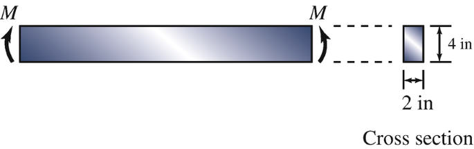
The beam with the cross section shown is subjected to couples M. The resulting maximum tensile stress in the beam is 3000 psi. Determine M.
Problem 6.122
-
6.123
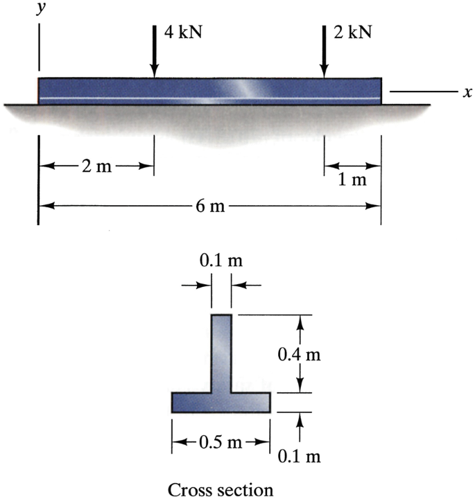
Assume that the surface on which the beam rests exerts a uniformly distributed load on it. Determine the maximum tensile and compressive stresses due to bending at x = 3 m.
Problem 6.123
-
6.124
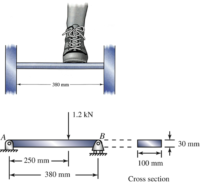
For a preliminary analysis of the ladder rung, model it as the simply supported beam AB with a 1.2-kN point force. What is the maximum magnitude of the normal stress in the rung?
Problem 6.124
-
6.125
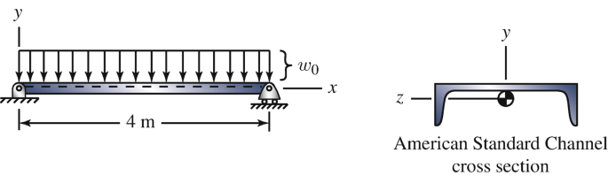
The beam has a C200X20.5 American Standard Channel cross section (see Appendix E) oriented as shown and consists of steel with yield stress σY = 360 MPa. The beam is subjected to a uniformly distributed load w0 = 1250 N/m, which includes the beam’s weight. (a) Determine the section modulus about the z axis. (b) What is the beam’s factor of safety?
Problem 6.125
-
6.126
If the C200X20.5 American Standard Channel cross section of the beam in Problem 6.125 is reoriented as shown, what uniformly distributed load w0 (which includes the beam’s weight) can the beam support with a factor of safety of 2?
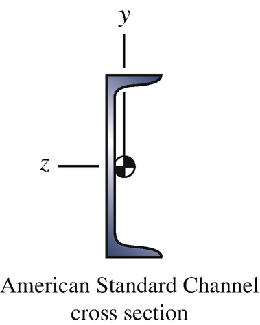
Problem 6.126
-
6.127∗
The value of the triangular distributed load at x = 4 m is w0 = 2 kN/m. The composite beam consists of two aluminum alloy beams (material A) with elastic modulus EA = 70 GPa that are bonded to a wood beam (material B) with elastic modulus EB = 12 GPa. What are the magnitudes of the maximum normal stresses in the aluminum alloy and in the wood at x = 2 m?
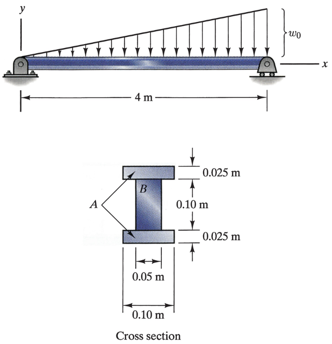
Problems 6.127–6.128
-
6.128∗
The composite beam consists of two aluminum alloy beams (material A) with elastic modulus EA = 70 GPa that are bonded to a wood beam (material B) with elastic modulus EB = 12 GPa. The yield stress of the aluminum alloy is 35 MPa and the yield stress of the wood is 14 MPa. What is the largest value of w0 for which yielding will not occur in either material?
-
6.129
The beam consists of elastic-perfectly plastic material with yield stress σY = 250 MPa. The force F = 80 kN. Determine the distance d and sketch the distribution of normal stress at x = 2 m.
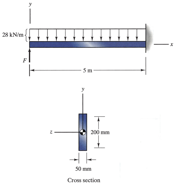
Problems 6.129–6.131
-
6.130
The beam consists of elastic-perfectly plastic material with yield stress σY = 250 MPa. The force F = 80 kN. At what axial position x is the distance d a minimum? What is the minimum value of d?
-
6.131
The beam consists of elastic-perfectly plastic material with yield stress σY = 250 MPa. If the force F is progressively increased from its initial value of 80 kN, at what value will the beam fail by formation of a plastic hinge? Where does the plastic hinge occur?
-
6.132∗
In terms of the coordinate system shown, the moments and product of inertia of the cross section are Iy = 4.633E‐6 m4, Iz = 7.158E‐6 m4, and Iyz = 4.320E‐6 m4. The beam is subjected to a moment M = 200 N‐m about the z axis. Determine the normal stress at point P.
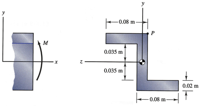
Problems 6.132–6.133
-
6.133∗
In terms of the coordinate system shown, the moments and product of inertia of the cross section are Iy = 4.633E‐6 m4, Iz = 7.158E‐6 m4, and Iyz = 4.320E‐6 m4. The beam is subjected to a bending moment about the z axis. Draw a sketch indicating the location of the neutral axis.
-
6.134
The beam is subjected to a distributed load. For the cross section at x = 0.6 m, determine the average shear stress (a) at the neutral axis and (b) at y′ = 0.02 m.
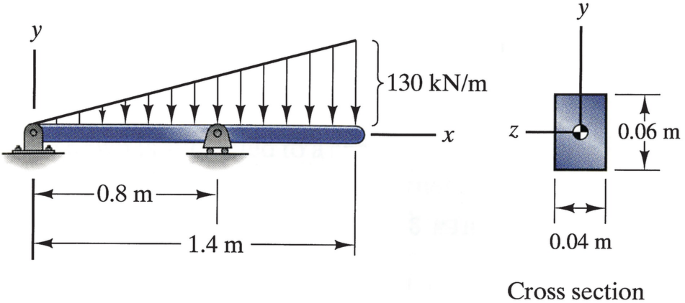
Problems 6.134–6.135
-
6.135
The beam is subjected to a distributed load. For the cross section at x = 1.0 m, determine the average shear stress (a) at the neutral axis and (b) at y′ = 0.02 m.
-
6.136
At a given axial position the beam whose cross section is shown is subjected to a shear force V = 2400 lb. What is the average shear stress at the neutral axis (y′ = 0)?
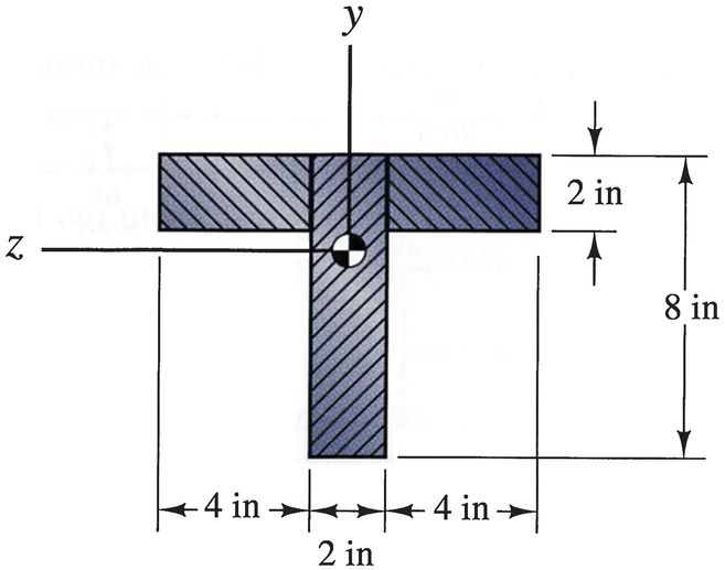
Problems 6.136–6.137
-
6.137
The beam whose cross section is shown consists of three planks of wood glued together. At a given axial position, it is subjected to a shear force V = 2400 lb. What are the magnitudes of the average shear stresses acting on each glued joint?


Rights and permissions
Copyright information
© 2020 Springer Nature Switzerland AG
About this chapter
Cite this chapter
Bedford, A., Liechti, K.M. (2020). Stresses in Beams. In: Mechanics of Materials. Springer, Cham. https://doi.org/10.1007/978-3-030-22082-2_6
Download citation
DOI: https://doi.org/10.1007/978-3-030-22082-2_6
Publisher Name: Springer, Cham
Print ISBN: 978-3-030-22081-5
Online ISBN: 978-3-030-22082-2
eBook Packages: EngineeringEngineering (R0)