
Abstract
Bars are subjected to axial torques in many engineering applications. The resulting stresses and deformations are analyzed in this chapter. A state of pure shear stress is first defined. In terms of a cartesian coordinate system with its axes perpendicular to the faces of a cubical element, a state of pure shear stress acting on the element is described by the components of stress σx = 0, σy = 0, σz = 0, τxy = τ, τyz = 0, and τxz = 0. For a linear elastic material, the only resulting nonzero strain component is γxy = τ/G, where G is the shear modulus. By passing an oblique plane through the cubical element and drawing the free-body diagram of the part of the element to one side of the plane, expressions for the normal and shear stresses on oblique planes are obtained. The results show that there is no plane on which the shear stress is larger in magnitude than τ, and the magnitudes of the maximum tensile and compressive stresses are equal to τ. Prismatic cylindrical bars subjected to torques T at the ends are then analyzed. The angle of twist of a bar of length L (the angle through which an end of the bar rotates relative to the other end, expressed in radians) is ϕ = TL/GJ, where J is the polar moment of inertia of the bar’s circular cross section. The shear stress in the bar at a radial distance r from the bar’s axis is τ = Tr/J. Examples of statically indeterminate problems are then presented, showing that the same procedure applied to axially loaded bars in Chapter 3 applies to problems involving torsional loading. Composite bars, consisting of bonded concentric cylindrical bars consisting of different materials, are analyzed, followed by bars with gradually varying cross sections and bars subjected to distributed torsional loads. Torsion of circular bars consisting of material exhibiting elastic-perfectly plastic behavior is covered. A discussion is given of an approximate solution for bars having cross sections consisting of hollow tubes with thin walls that need not be circular. The chapter closes with a discussion of design considerations applying to bars subjected to torsion.
Access this chapter
Tax calculation will be finalised at checkout
Purchases are for personal use only
Author information
Authors and Affiliations
Appendices
Chapter Summary
4.1.1 Pure Shear Stress
In Fig. (a), a cube of material is subjected to a state of pure shear stress. The shear strain is related to the shear stress by


The shear modulus G is given in terms of the modulus of elasticity E and Poisson’s ratioν by
4.1.2 Stresses on Oblique Planes
The normal and shear stresses on a plane \( \mathcal{P} \) oriented as shown in Fig. (b) are


There is no value of θ for which the shear stress is larger in magnitude than τ. The maximum tensile and compressive stresses occur at θ = 45º where σθ = τ and at θ = 135º where σθ = − τ.
4.1.3 Torsion of Prismatic Circular Bars
Consider a cylindrical bar of length L and radius R subjected to an axial torque T (Fig. (c)). The resulting angle of twist of the end of the bar is
where
is the polar moment of inertia of the bar’s cross-sectional area about its axis. The shear stress on the plane shown at a distance r from the bar’s axis is


Equations (4.7) and (4.9) also apply to a bar with a hollow circular cross section. In that case the polar moment of inertia is given by
where Ri and Ro are the bar’s inner and outer radii.
4.1.4 Statically Indeterminate Problems
Solutions to problems involving torsionally loaded bars in which the number of unknown reactions exceeds the number of independent equilibrium equations involve three elements: (1) relations between the torques in bars and their angles of twist, (2) compatibility relations imposed on the angles of twist by the geometry of the problem, and (3) equilibrium.
4.1.5 Bars with Gradually Varying Cross Sections
If the polar moment of inertia is a gradually varying function of axial position J(x) (Fig. (d)), the stress distribution on a plane perpendicular to the bar’s axis at axial position x can be approximated by


The angle of twist of the bar is
4.1.6 Distributed Torsional Loads
A distributed torsional load on a bar can be described by a function c defined such that the axial torque on each element dx of the bar is c dx (Fig. (e)).


4.1.7 Torsion of an Elastic-Perfectly Plastic Circular Bar
The elastic-perfectly plastic model of shear stress-shear strain behavior is shown in Fig. (f). If the shear strain at the bar’s outer surface does not exceed the value γY corresponding to the yield stress, the shear stress distribution is given by Eq. (4.9) and the angle of twist by Eq. (4.7). If the shear strain does exceed the value corresponding to the yield stress at some radial position rY, the shear stress distribution is as shown in Fig. (g). The torque T and radial distance rY satisfy the equilibrium equation:


The upper bound of the torque the bar will support is obtained by setting rY = Ri in Eq. (4.22). The bar’s angle of twist is
4.1.8 Torsion of Thin-Walled Tubes
Consider a prismatic tube whose wall thicknesst is small compared to the lateral dimensions of the tube (Fig. (h)). The shear flowf is given by
where A is the cross-sectional area of the tube (Fig. (i)). The angle of twist of the tube is
where s measures distance along the circumference of the wall relative to some reference point.


4.1.9 Design Issues
A criterion that can be used for the design of bars subjected to torsion is to insure that the maximum magnitude of the shear stress does not exceed a shear yield stress τY, or some specified fraction of the shear yield stress, the allowable shear stress τallow. The factor of safety is defined by
If it is assumed that the shear yield stress is given in terms of the normal yield stress σY measured in a tensile test by \( {\tau}_{\mathrm{Y}}=\frac{1}{2}{\sigma}_{\mathrm{Y}} \), the factor of safety can be expressed in terms of the allowable shear stress and the normal yield stress given in Appendix B:
Review Problems
-
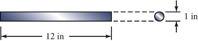
4.116
The prismatic bar is 12 in long and has a circular cross section with 1-in diameter. In a test to determine its elastic properties, the bar is subjected to 113-kip axial loads. After the loads are applied, the bar’s length is 12.054 in and its diameter is 0.9986 in. What is the shear modulus of the material?
Problem 4.116
-
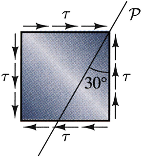
4.117
The cube of material is subjected to a pure shear stressτ. If the normal stress on the plane \( \mathcal{P} \) is −20 ksi, what is τ?
Problems 4.117–4.118
-
4.118
The cube of material is subjected to a pure shear stress τ. The shear modulus of the material is G = 4E6 psi. If the normal stress on the plane \( \mathcal{P} \) is −12 ksi, what is the shear strain of the cube?
-
4.119
The cross section of a portion of a propeller’s shaft is shown. If the engine exerts a 2200 N-m torque on the shaft, what is the magnitude of the maximum shear stress in the shaft?
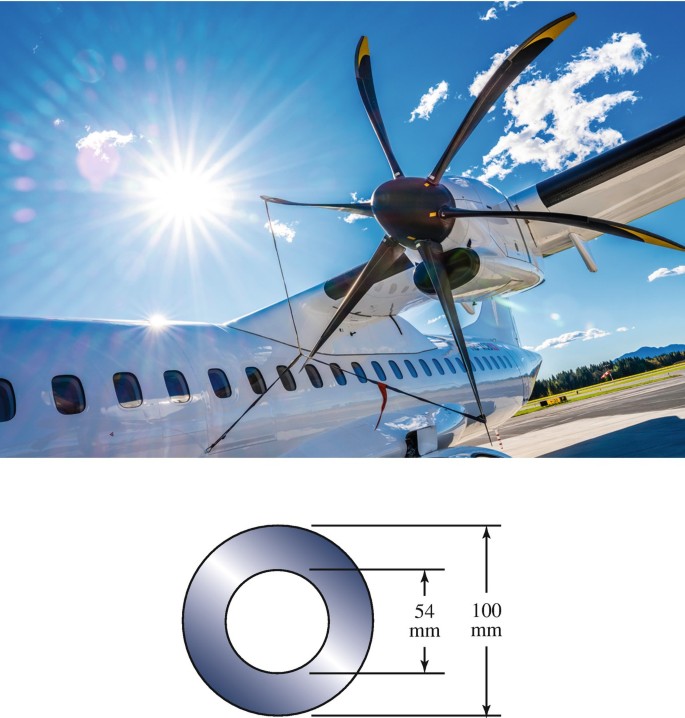
Problems 4.119–4.120 (Photograph from iStock by vm)
-
4.120
The cross section of a portion of the propeller’s shaft is shown. The shaft is made of material with shear modulus G = 220 GPa. The engine exerts a 2200 N-m torque on the shaft. If the length of the portion of shaft is 0.6 m, what is its angle of twist?
-
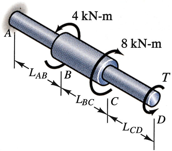
4.121
The lengths LAB = LBC = 200 mm and LCD = 240 mm. The diameter of parts AB and CD of the bar is 25 mm and the diameter of part BC is 50 mm. The shear modulus of the material is G = 80 GPa. If the torque T = 2.2 kN‐m, determine the magnitude of the angle of twist of the right end of the bar relative to the wall in degrees.
Problems 4.121–4.122
-
4.122
The lengths LAB = LBC = 200 mm and LCD = 240 mm. The diameter of parts AB and CD of the bar is 25 mm and the diameter of part BC is 50 mm. The shear modulus of the material is G = 80 GPa. What value of the torque T would cause the angle of twist of the right end of the bar relative to the wall to be zero?
-
4.123
The radius R = 200 mm. The infinitesimal element is at the surface of the bar. What are the normal stress and the magnitude of the shear stress on the plane \( \mathcal{P} \)?
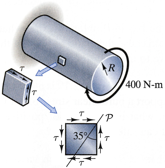
Problem 4.123
-
4.124
The radius R = 200 mm. The infinitesimal element is at the surface of the bar. What are the normal stress and the magnitude of the shear stress on the plane \( \mathcal{P} \)?
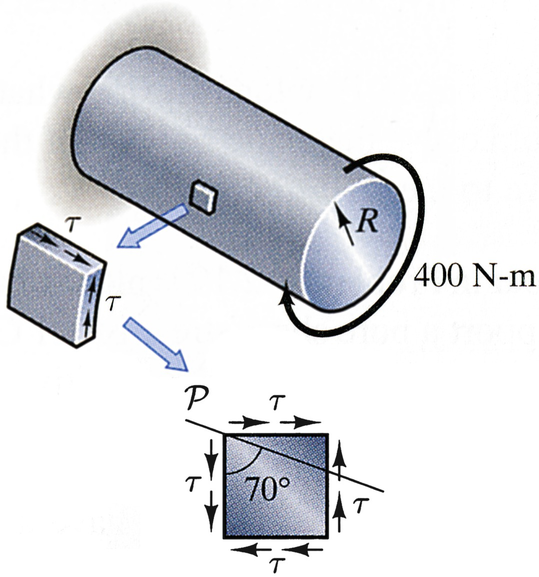
Problem 4.124
-
4.125
Part AB of the bar has a solid circular cross section, and part BC has a hollow circular cross section. The bar is fixed at both ends and a 150-in-kip axial torque is applied at B. Determine the magnitudes of the torques exerted on the bar by the walls at A and C.
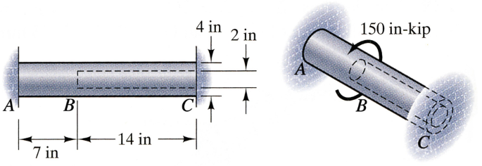
Problems 4.125–4.127
-
4.126
Part AB of the bar has a solid circular cross section and part BC has a hollow circular cross section. The bar is fixed at both ends and a 150-in-kip axial torque is applied at B. Determine the magnitudes of the maximum shear stresses in parts AB and BC.
-
4.127∗
Part AB of the bar has a solid circular cross section and part BC has a hollow circular cross section. The bar is fixed at both ends and a 150-in-kip axial torque is applied at B. Suppose that you want to decrease the weight of the bar by increasing the inside diameter of part B. The bar is made of material that will safely support a pure shear stress of 10 ksi. Based on this criterion, what is the largest safe value of the inside diameter?
-
4.128
The aluminum alloy bar has a circular cross section with 20-mm diameter and a shear modulus of 28 GPa. What is the magnitude of the maximum shear stress in the bar due to the uniformly distributed torque?
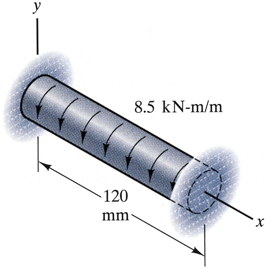
Problems 4.128–4.129
-
4.129
The aluminum alloy bar has a circular cross section with 20-mm diameter and a shear modulus of 28 GPa. What is the magnitude of the bar’s angle of twist (in degrees) relative to the walls at x = 60 mm?


Rights and permissions
Copyright information
© 2020 Springer Nature Switzerland AG
About this chapter
Cite this chapter
Bedford, A., Liechti, K.M. (2020). Torsion. In: Mechanics of Materials. Springer, Cham. https://doi.org/10.1007/978-3-030-22082-2_4
Download citation
DOI: https://doi.org/10.1007/978-3-030-22082-2_4
Publisher Name: Springer, Cham
Print ISBN: 978-3-030-22081-5
Online ISBN: 978-3-030-22082-2
eBook Packages: EngineeringEngineering (R0)